Friday, April 25, 2014

Post 26: Moving forward by looking rearward

OK, so I turned the frame around in the garage to weld seams on the back half, and now I can't get the engine and tranny back in to mess with the motor mounts.  What to do?

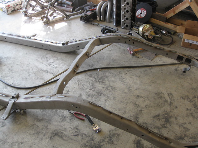
Work on the rearend, that's what.  I've been staring at this Explorer 8.8" rearend for months now, and I'm finally at the point where I can do something with it.

The first order of business: modify the Explorer shock mount/u-bolt bracket plate thingies ("plates," from this point on) to work with the narrower '54 springs.  Two differences between the original Ford and new Explorer setups are a larger diameter axle tube (3.00" old vs. 3.25" new) and larger leaf spring width (2" old vs. 3" new (actually, the Explorer might be 2.5", but it doesn't really matter)).  I know the plates could work without modification, as my dad just put an Explorer rearend in his Chevy and didn't change anything.  However, because I know the extra gap between the u-bolts and leaf springs will eternally bother me and because I am in a welding kind of mood, I decided to mess with them a bit.

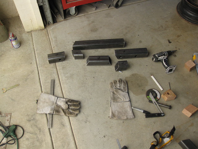
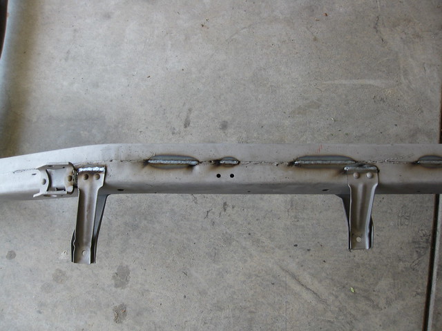
I started by welding the factory holes closed.

031

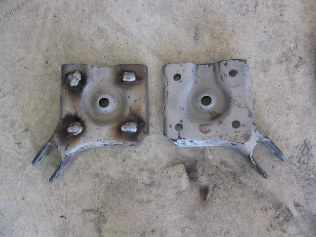
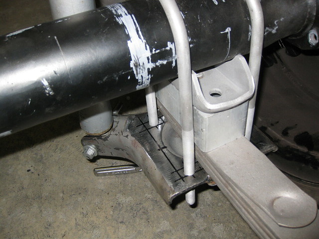
Then I ground them smooth and realized that the "dip" or "valley" at the back of the plates is wide enough that they might shift around on the narrow Ford leaf springs. I cut a few pieces of scrap metal to fill the valley, welded them in quickly, not caring about appearance for once, and then dressed the welds on the top to get the spring mounting surface fairly flat.

002

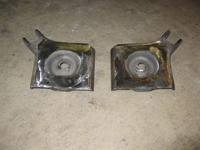
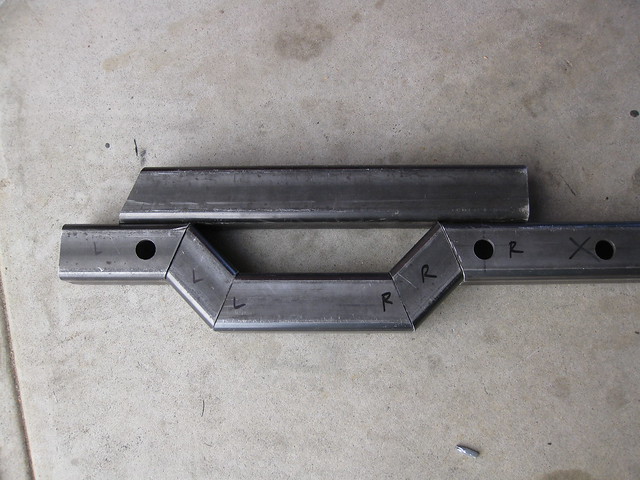
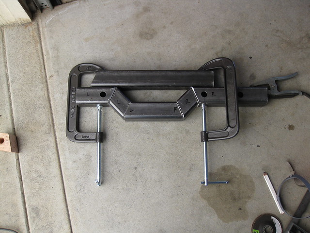
I spent more time than I expected laying out the hole pattern to drill. It's tough when none of the plate edges are square or even straight, and I ended up measuring out from the center of the middle hole.

008

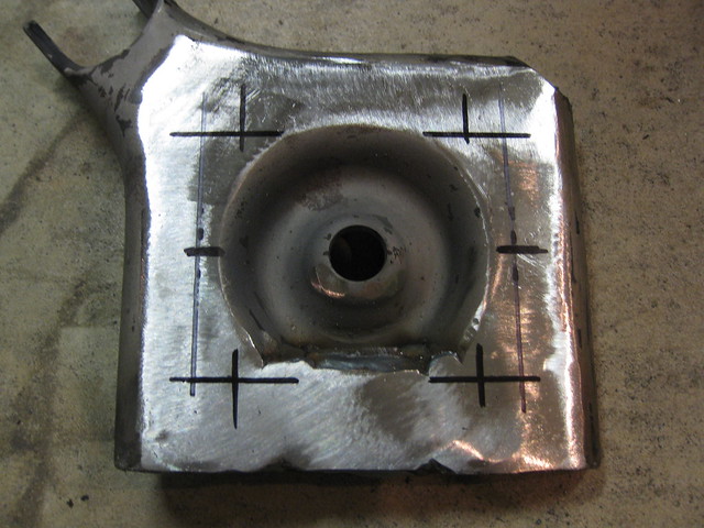
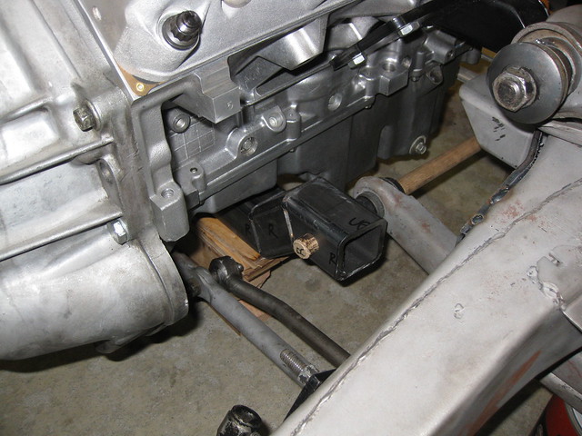
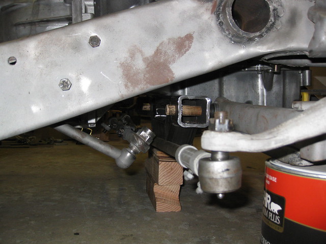
The u-bolts are 1/2" thread and will be spread apart 3.25" inches, so those holes were easy to locate. The distance between each pair of u-bolts was trickier. I was going to leave exactly 2 inches of room, since that's how wide the leaf springs are and the whole point of this exercise is to take up all slack in the assembly. Fortunately, I didn't start drilling at that point. First, my lowering blocks are wider than 2 inches. Second, the leaf spring perches that I will eventually weld onto the axle tubes are even wider than the lowering blocks. When everything was accounted for, I coincidentally wound up drilling the holes 3" apart on center, which is exactly what the original '54 plates were. There's definitely a gap on either side of the leaf spring, but that's how it looked on the old rearend and it worked just fine.

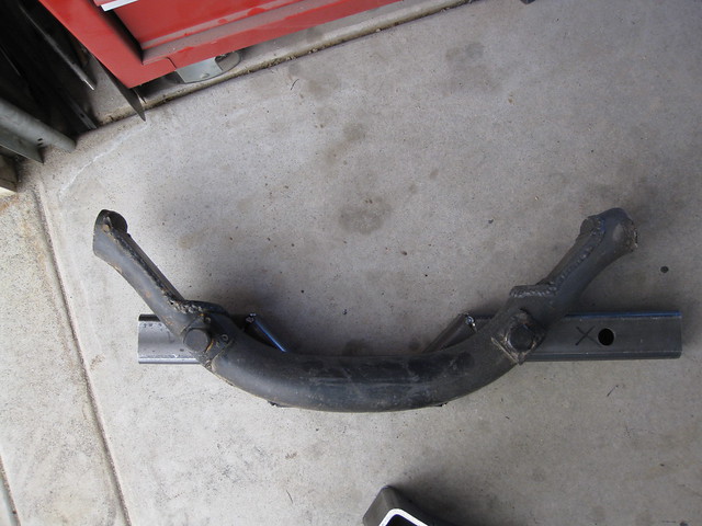
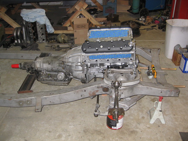
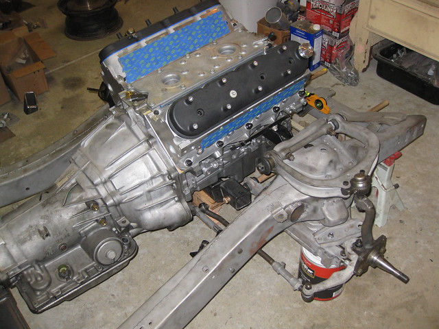
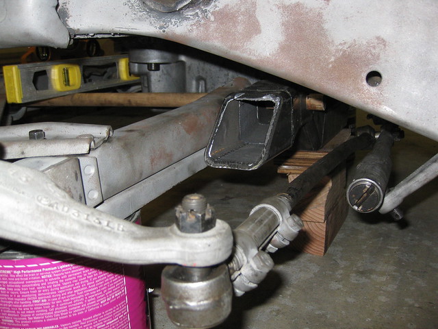
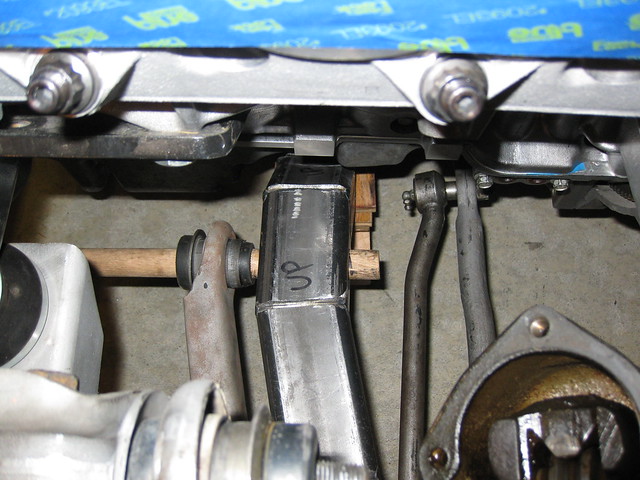
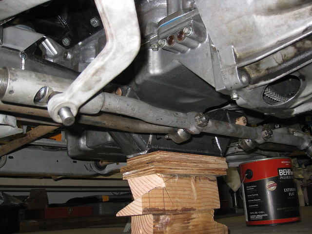
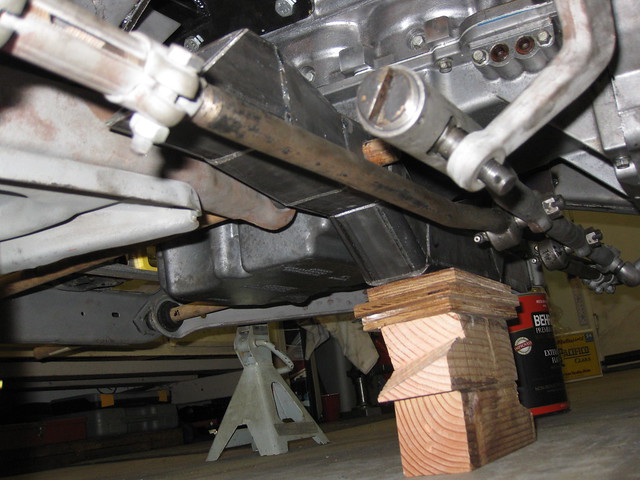
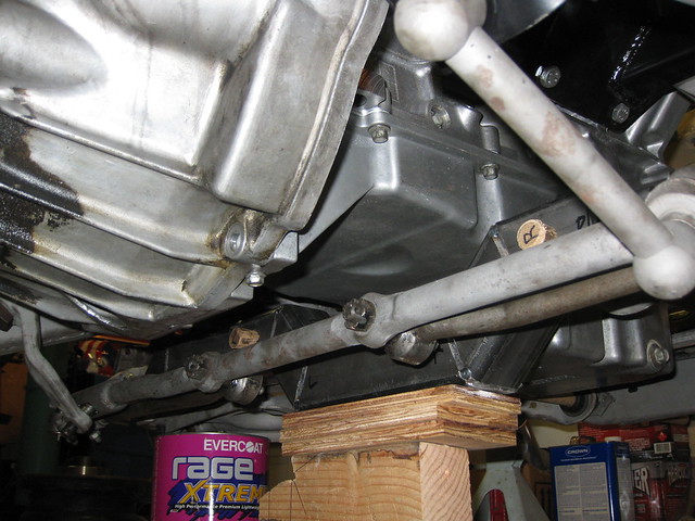
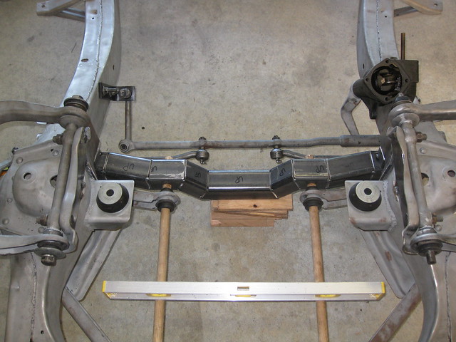
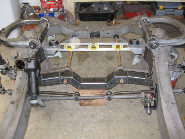
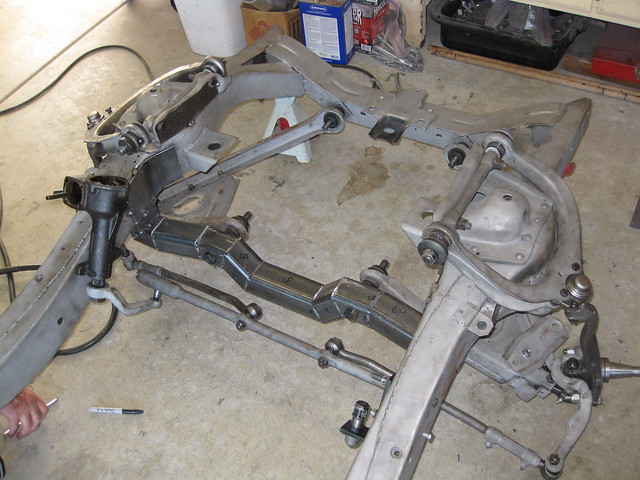
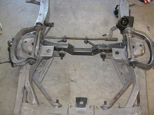
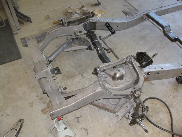
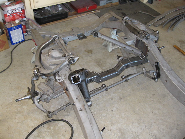
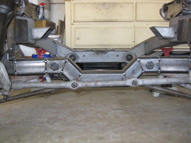
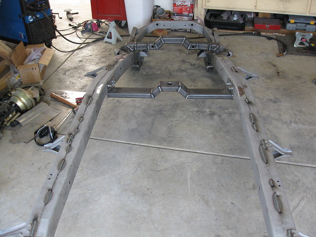
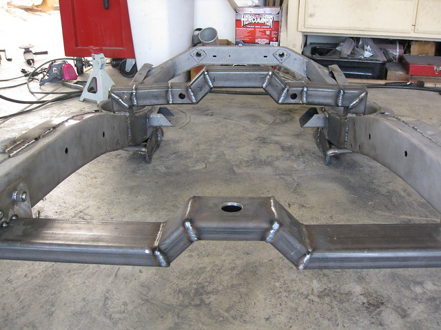
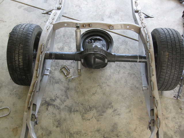
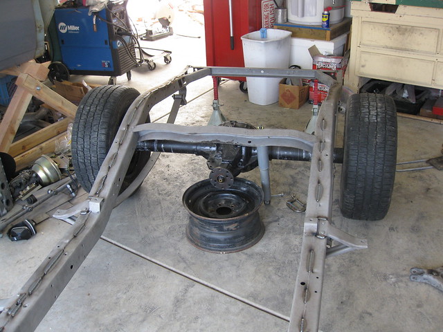
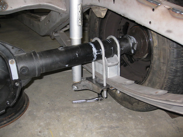
I drilled the holes, put one side of the suspension back together for mock-up, and bolted the plate in place. Obviously, the leaf spring in the pictures below isn't put together correctly. I had the long spring hooked up over the weekend when I first slid the rearend in place, and tonight I just threw the extra springs back in there to give me the right thickness. The first few pictures are from the weekend, and the last two are from tonight.

037

038

042

046

047

010

011

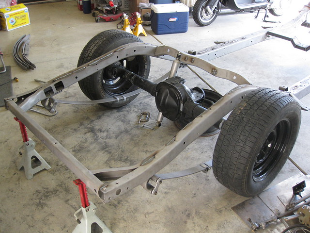
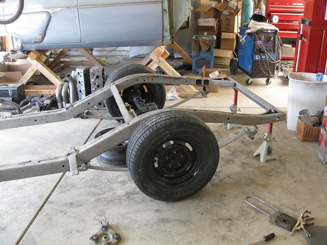
No, those aren't the wheels and tires I'm going to use, although it would be nice to get a tire that wide in there. Those are my dad's old tires on some new universal bolt-pattern GM Rally wheels, which my dad scored at a tire shop for 100 bucks (!). He went in to get his new tires mounted on his first set of brand-new Rallys, purchased from Summit for about $300, and the guy at the shop told him about this other set.  It was a bummer than he already spent the money at Summit, but he bought the second set from the guy anyway because it was a killer deal and he knew I needed a set of wheels to roll Maude around on for the time being.

That's as far as I made it today.  This weekend I hope to get the other plate done and make some upper shock mounts.  If I have time I will start working on the motor mounts, too.

Tuesday, April 22, 2014

Post 25: Sunless tanning

Nope, not with lotion. I'm talking about a farmer tan from welding. Or at least a burn. Still, no sun required!

I haven't posted in weeks, I know. I always read blogs and forums where guys are saying, "I haven't had a chance to work on the car or post on this thread because I've been so busy at work," and I think to myself, how busy can you get? I mean I work full-time and have a family and chores and other stuff going on but I still manage to get some car time sqeezed in.

Or at least I used to.

Seriously, I haven't posted in weeks because I've been so freakin' busy. Work has been nuts since about mid-March, weekends fill up with birthday parties, baseball games, Easter stuff, more work... Now I understand.

Anyway, even though I haven't posted, I have managed to be productive around all the other goings-on in my life. Actually, I've passed another couple of major milestones. Let me show you.

First, I finished assembling as much of the engine as I need to at this point. By that I mean it's together enough to use for mock-up purposes in the frame and so that no foreign material can find its way in. I didn't bother with any front dress or intake stuff because it just makes the engine heavier and harder to move around with the cherry picker.

More importantly, I worked on, scrapped, reconfigured, built, and welded in my new engine crossmember. Remember this plan?

003

004

005

Well, after I dropped the drivetrain back in and bolted on a few suspension parts, I realized that my design wasn't really any better than Ford's. It was too close to the oil pan and didn't create enough exhaust clearance to warrant the headache of cutting all those compound angles out of steel. So I went back to the drawing board, relying on fewer angles, more individual pieces, and my own welding skill (which is limited, but pretty good when working with 1/8" to 1/4" thick material). It took some time, but here's what I came up with in the end.

006

007

008

009

The most nerve-wracking part was honestly drilling the 7/8" holes for the control arm bolts. Here's the point at which I knew I was going to be okay.

010

011

I did a lot of test-fitting with the assembled engine including headers, which don't actually clear the front suspension anymore. I think adding the reinforcement plates to the upper A-arm hats and changing the overall angle of the drivetrain caused a few issues. However, neither of those things are set in stone, and I'm confident that everything will fit again when I'm done. At this point the clearance didn't really matter - I was just trying to see how much room I had for the pipe exiting the header compared to the Ford crossmember (answer: much more).

012

013

015

016

Eventually I realized that I needed the full suspension and steering back on the car. I was really trying to avoid this, because I felt like it would take a lot of time and I'd get even more fingerprints all over the bare metal parts that would rust up immediately (even when I'm wearing gloves this manages to happen). However, one night I was out in the garage after the kids went to bed and I finally stopped staring at the parts and put them together. It really didn't take long and it ended up being fun, plus it was a good use of my free time when I couldn't make a bunch of power tool noise.

001

002

003

005

Amazingly, frame, suspension, and engine are all still level.

006

007

008

009

I tried to keep the flat part of the crossmember as close to and at the same angle as the lower control arm.

011

Because I can't help myself, I was still toying with the idea of moving the drivetrain forward a bit. This would primarily be for bellhousing-to-firewall clearance, which I had plenty of before but now that I've moved the transmission mount up about an inch I'm nervous. However, once I got the steering reassembled I confirmed that I put the drivetrain where it is for a good reason: the steering barely clears the oil pan (to the rear) as the wheels turn lock-to-lock. There's no way I can go forward, but I am still thinking I'll modify my motor mounts to drop the engine down another degree or so. I may also push the rear of the transmission up. I'd like the drivetrain to be more level than it is, and this would alleviate my newly-created header-to-frame interference problem.

012

013

014

This is the final shape, long enough to reach both sides of the frame but without the vertical pieces attached (I was still figuring them out when I took these pictures).

016

017

018

019

020

This is after I figured the ends out, tack-welded it in, and tried bolting the suspension on to see if it articulated correctly.

021

022

024

025

026

After this, while my dad was still at my house, he helped me start to make things permanent by holding the frame up in various positions while I welded with gravity on my side (because I'm not nearly as passable of a welder when I'm going vertically or upside-down).

028

029

030

This is where I really started working on the tan. I welded up the engine crossmember, transmission crossmember (except for the very ends, in case I still need to adjust things), A-arm reinforcement plates, the curved plates that cover the giant holes in the frame left when I cut out the old crossmember, and then I even went down the length of the frame rails, welding up the seams wherever the factory decided to save money by not doing that.

032

033

034

035

036

My next post will be about the rearend, which I'm starting to align and set up in the frame. Stay tuned.